IRIS 1
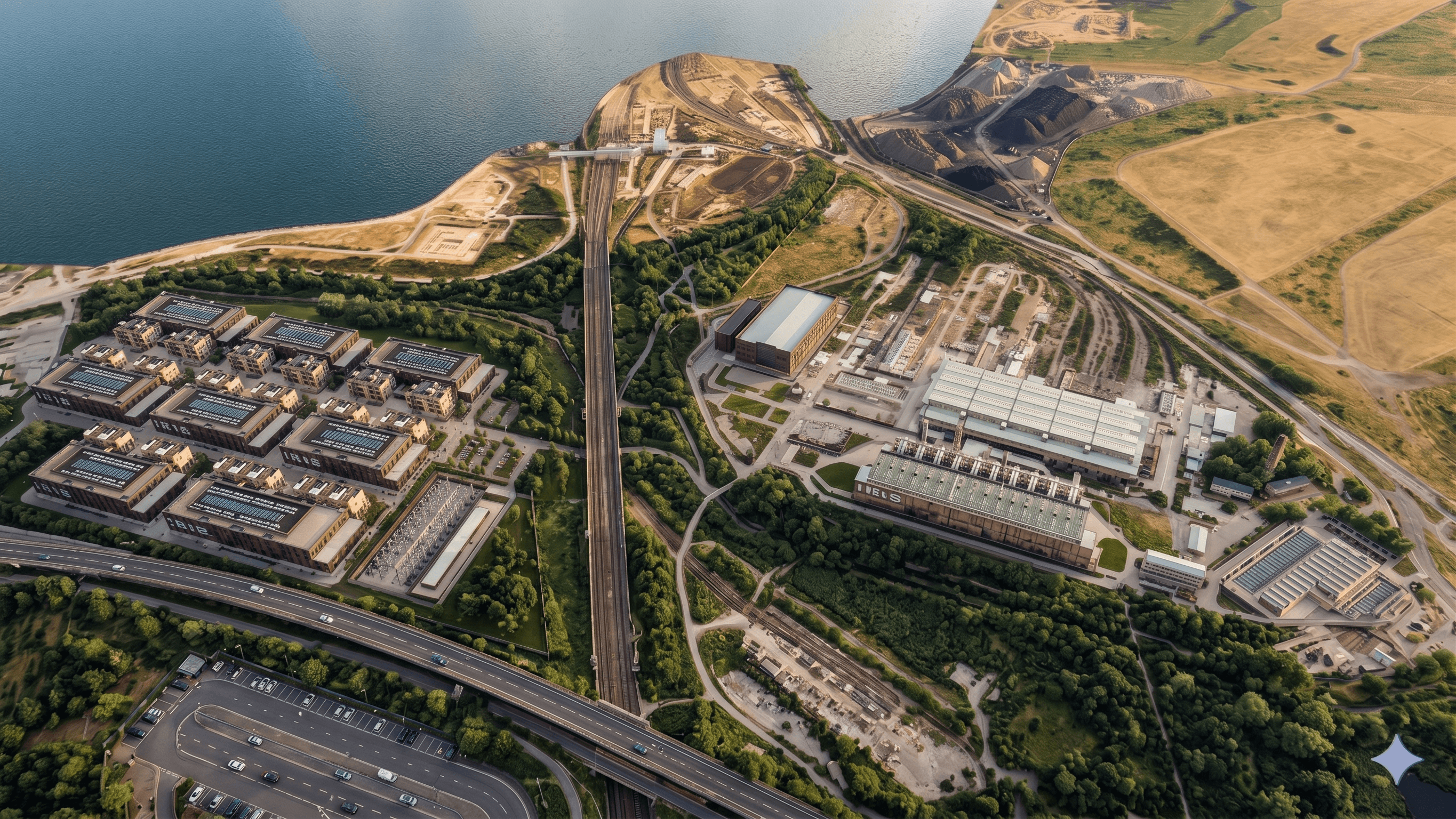
Bluesio's flagship 48 MW IT facility in Most, Czech Republic — a three-storey, twelve-hall campus engineered for hybrid air and direct liquid cooling at hyperscale density.


Overview
A campus built for phased hyperscale delivery
The IRIS 1 campus sits on a 50,225 sqm plot across two adjoining sites: the Main Plot, housing the data centre and office buildings, and the Generators Yard, dedicated to incoming power and emergency generation. The production building rises three storeys, each carrying four data halls, with a rooftop cooling plant above and a six-storey office building connected via an entrance gallery.
Power provision runs as a dedicated package aligned to the site's build programme: an 80 MW / 35 kV medium-voltage supply from CEZ/SEVEN, sized to bring the full 48 MW IT campus online in step with tenant demand rather than a single fixed delivery date.

Gross Site Area
Max Development Floor Area
MW
Incoming Grid Feed (35 kV)
IT Load per m² of Land

Specifications
Facility Specifications
IRIS 1 is designed as a 48 MW IT data centre in Most, Czech Republic — a three-storey production building with four data halls per floor, twelve halls in total. The facility is electrically divided into four independent 12 MW IT blocks, each spanning three stacked data halls, giving tenants a modular path to scale power, density, and cooling strategy hall by hall.
Built to Tier III standards for concurrent maintainability, the campus draws an 80 MW / 35 kV medium-voltage supply from CEZ/SEVEN, with a dedicated Generators Yard housing emergency power and fuel storage separate from the main production building.
75 MW
Total Power
48 MW
IT Load
12
Data Halls
~14,484 sqm
Whitespace (12 × 1,207 sqm)
1.24
Annualised PUE (100% load)
1.5
Worst-Case PUE
0.00
WUE — No Adiabatic Cooling
4 × 12 MW
Flexible IT Blocks
3-Storey
Production Building Architecture
1,207 sqm
Per Data Hall
3.31 kW/sqm
Base Data Hall Density
Tier III
Concurrently Maintainable Design
35 kV
Incoming Grid Supply (80 MW max)
N+1
Electrical Redundancy (4M3 Topology)
48-Hour
Backup Fuel Storage
50,225 sqm
Gross Site Area
Architecture
Power Architecture
The electrical system steps down from a 35 kV incoming feed through 11 kV to 0.4/0.23 kV, guaranteeing N+1 redundancy across both IT and mechanical loads. Generator power plants operate at 11 kV in N+1 configuration, feeding 11 kV rings to their corresponding transformers, with low-voltage distribution run in a four-to-make-three (4M3) topology.
Each 4M3 system carries four independent 3.5 MVA power modules with 2.25 MW of UPS capacity, backed by VRLA batteries rated for five minutes of autonomy — enough to bridge to generator start, with 48 hours of on-site diesel storage behind that. IT loads are supplied in A/B redundancy across two independent supply systems, with air-conditioning loads distributed across the same eight power paths, isolating any single fault from affecting neighbouring systems or the data halls.
01
N+1 Redundant Distribution
11 kV generator rings and transformer rings both run N+1; LV distribution follows a 4-to-make-3 (4M3) topology.
02
A/B Load Supply
IT and mechanical loads supplied via two independent A/B systems per area, with no cross-system fault propagation.
03
35 kV Grid Supply
Dedicated incoming feed from CEZ/SEVEN, up to 80 MW, stepping down through 11 kV to 0.4/0.23 kV.
04
5-Minute UPS Autonomy
Static UPS (2×1,125 kVA per module) on VRLA batteries, bridging to generator start.
05
48-Hour Fuel Storage
12 × 80,000 l underground diesel tanks in the Generators Yard, sized for 48 hours of full-load runtime.
06
73.4 MVA Design Load
Preliminary maximum campus power demand at 0.96 capacitive power factor, full load.
Philosophy
Modular by design, flexible by tenant
Each of the four 12 MW IT blocks corresponds to three stacked data halls, one above the other — mechanical and electrical distribution is engineered around this 12 MW modularity. How power is split across those three halls is a tenant decision, and it directly shapes rack density, busbar strategy, and cooling distribution. Three reference scenarios illustrate the range:
Balanced
4–4–4 MW
Mixed density
6–3–3 MW
HPC-weighted
8–2–2 MW
Mechanical
Cooling Strategy
Cooling runs on two independent water loops — chilled water for air cooling (AC) and a dedicated direct liquid cooling (DLC) loop — giving tenants a flexible split between conventional air-cooled racks and high-density GPU deployments. The AC loop cools data hall air through fanwall units; the DLC loop removes heat directly from the CPU/GPU die, designed against the Nvidia GB200's 35°C supply-temperature requirement — the most demanding spec in the market at time of design.
Twin DN350 rooftop rings feed twelve free-cooling chillers (N+2 redundant) supplying up to ten fanwall units per data hall and two CRAH units per electrical room on the AC side. On the DLC side, seven N+2 dry cooler units and seven water pumps feed up to eight CDUs per data hall, with seven heat exchangers bridging the two loops so chiller capacity can support DLC when ambient conditions push dry coolers past their limit.
Features
Infrastructure Features
A campus built at hyperscale
CDU-served rack loops designed to Nvidia GB200-class 35°C supply temperatures.
Hybrid Air & Liquid Cooling
Independent AC and DLC water loops, cross-connected via heat exchangers for shared freecooling capacity.
N+2 Free-Cooling Chillers
Twelve rooftop free-cooling chillers deliver freecooling for ~99% of annual operating hours.
N+1 Redundant Power Architecture
4M3 low-voltage topology with A/B supply redundancy across IT and mechanical loads.
35 kV Grid Supply
Dedicated CEZ/SEVEN medium-voltage feed, up to 80 MW available capacity.
48-Hour Backup Fuel Storage
Underground diesel tanks in a dedicated Generators Yard, isolated from the production building.
Modular 12 MW IT Blocks
Four electrically independent blocks, each spanning three stacked data halls.
Tier III Concurrent Maintainability
Facility-wide design supporting maintenance without service interruption.
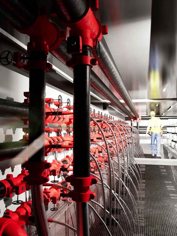
Hybrid LPWM system protecting data halls, MMRs, UPS and battery rooms.
Suppression
Fire Detection & Suppression
IRIS 1 uses a hybrid low-pressure water mist (LPWM) system as the primary building protection measure across the critical infrastructure — data halls, MMR rooms, UPS rooms, and battery rooms — with sprinkler protection reserved for the production building lobby given its longer evacuation routes. High-sensitivity smoke detection (HSSD) is deployed within data halls and CRAH spaces using chilled water.

Data Halls, MMR & UPS Rooms
Low-pressure water mist, with HSSD early-warning smoke detection.
Technical Spaces
Water mist space provision across switch rooms, generator rooms, fuel storage and technical corridors.
Loading, Storage & Office Areas
Water mist space provision throughout, plus portable extinguishers per local sector regulation.
Let’s Build The Future Of AI Together
Join us in building Europe’s most advanced AI and cloud infrastructure campus.